Sensors · RL-HSB-001
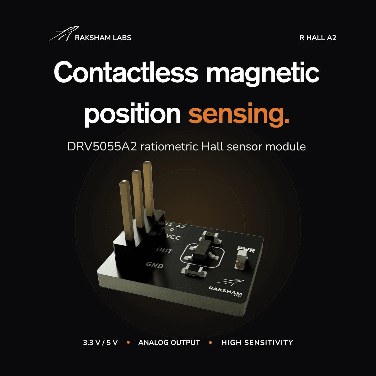
DRV5055A2 Hall Sensor Breakout Board
A general-purpose ratiometric ±42 mT linear Hall-effect breakout on three pins, providing drop-in analog magnetic-field sensing for position, RPM, current, and bench measurement on any microcontroller ADC.
A linear, ratiometric magnetic-field sensor on a three-pin breakout.
A general-purpose analog Hall-effect breakout that puts magnetic flux density on a microcontroller ADC pin, not a digital switch state.
The Raksham Labs DRV5055A2 Hall Sensor Breakout Board exposes a linear, ratiometric analog Hall-effect sensor on a simple three-pin header. Plug it into any 12-bit microcontroller ADC and you get a continuous reading of magnetic flux density for position, current, RPM, and field-strength measurement, all from the same part.
Because the output is ratiometric (zero-field at VCC/2, sensitivity that scales with supply), the cleanest readings come from powering the sensor and the ADC reference from the same rail. Typical sensitivity is 50 mV/mT at 5 V over a ±42 mT linear range, with 20 kHz of bandwidth, fast enough for motor RPM pickups and current waveform capture.
The board includes one red LED to show that VCC is present. The LED is only a power indicator; the measured Hall signal is available on the center OUT pin.
Use it for:
- Joysticks, gimbals, throttles, pedals, levers
- Rotary knobs and angle sensing with a magnet
- Linear position sensing with a sliding magnet
- Proximity or displacement sensing
- Robotics actuator feedback
- Door/lid/open-close position sensing
- End-stop detection using analog thresholds
- Motor or mechanism position feedback
- Magnetic field measurement or calibration fixtures
- Current sensing, if paired with the right magnetic path/core
At a glance.
Detailed electrical and mechanical drawings are linked from the documentation section. Values are typical; consult the IC datasheet for guaranteed limits.
- Sensor IC
- TI DRV5055A2 linear Hall-effect sensor
- Supply voltage
- 3.3 V or 5 V nominal
- Recommended VCC
- 3.0-3.63 V / 4.5-5.5 V
- Output
- Ratiometric analog voltage
- Zero-field output
- VCC / 2 typical
- Sensitivity
- 50 mV/mT at 5 V; 30 mV/mT at 3.3 V
- Linear field range
- ±42 mT at 5 V; ±44 mT at 3.3 V
- Bandwidth
- 20 kHz typical
- Pins
- VCC, OUT, GND; OUT is center pin
- Indicator
- Red power LED
- Included
- Breakout board and header pins
- Sensor temp range
- -40°C to 125°C
- Country of origin
- India
How it works & how to wire it.
Integration notes, pinouts, and example code. Datasheet downloads coming soon. Engineering support is one form away.
How it works
The DRV5055A2 outputs approximately VCC / 2 when no magnetic field is present. As
magnetic flux density through the sensor changes, OUT moves linearly above or below
that midpoint. Because the output is ratiometric, the cleanest ADC readings come from
powering the breakout from the same voltage used as the ADC reference.
For the A2 option, typical sensitivity is 50 mV/mT at 5 V and 30 mV/mT at
3.3 V. The typical linear magnetic field range is about ±42 mT at 5 V and
±44 mT at 3.3 V.
Integration
Connect VCC to a nominal 3.3 V or 5 V rail, connect GND to the controller
ground, and connect the center OUT pin to an ADC input. Use 3.0-3.63 V or
4.5-5.5 V supply rails for predictable DRV5055 sensitivity.
Place the magnet so its field passes perpendicular to the top face of the Hall sensor. If the voltage moves in the opposite direction from what your firmware expects, invert the sign in software or reverse the magnet orientation.
Header pins are included with the board in the package. Solder them before use if your setup needs breadboard, jumper-wire, or socketed connections.
Pinout
The header is VCC, OUT, and GND, with OUT in the center. Always check the PCB silkscreen before applying power.
- VCC
- 3.3 V or 5 V nominal supply. Tie this to the same rail used as the ADC reference for ratiometric tracking.
- OUT
- Center pin · ratiometric analog output for ADC. Sits at VCC / 2 at zero field.
- GND
- Ground. Connect to the controller ground reference.
Mechanical drawing
Board envelope and side profile. All dimensions in millimetres; the sensing IC, not the connector edge, is the magnetic reference point.
ADC conversion · STM32 HAL
A 12-bit ADC where the reference equals the board VCC. Adjust sensitivity per supply voltage.
// Example for a 12-bit ADC where the ADC reference equals the board VCC.
uint16_t raw = HAL_ADC_GetValue(&hadc1);
float vcc = 3.3f;
float sensitivity = 0.030f;  // V/mT for DRV5055A2 at 3.3 V

float vout = (raw / 4095.0f) * vcc;
float field_mT = (vout - (vcc / 2.0f)) / sensitivity;Questions, answered.
If your question is not here, write to engineering. We usually reply within a working day.