Navigation · RL-GNSS-001
KAMAL NAV GM1 GNSS Module
L1/L5 dual-band GNSS receiver with 3-axis magnetometer, tuned for UAV navigation.
A dual-band, multi-constellation navigation receiver for autonomous UAVs.
L1+L5 for multipath rejection. Integrated magnetometer for compass heading. One JST SH cable to your flight controller.
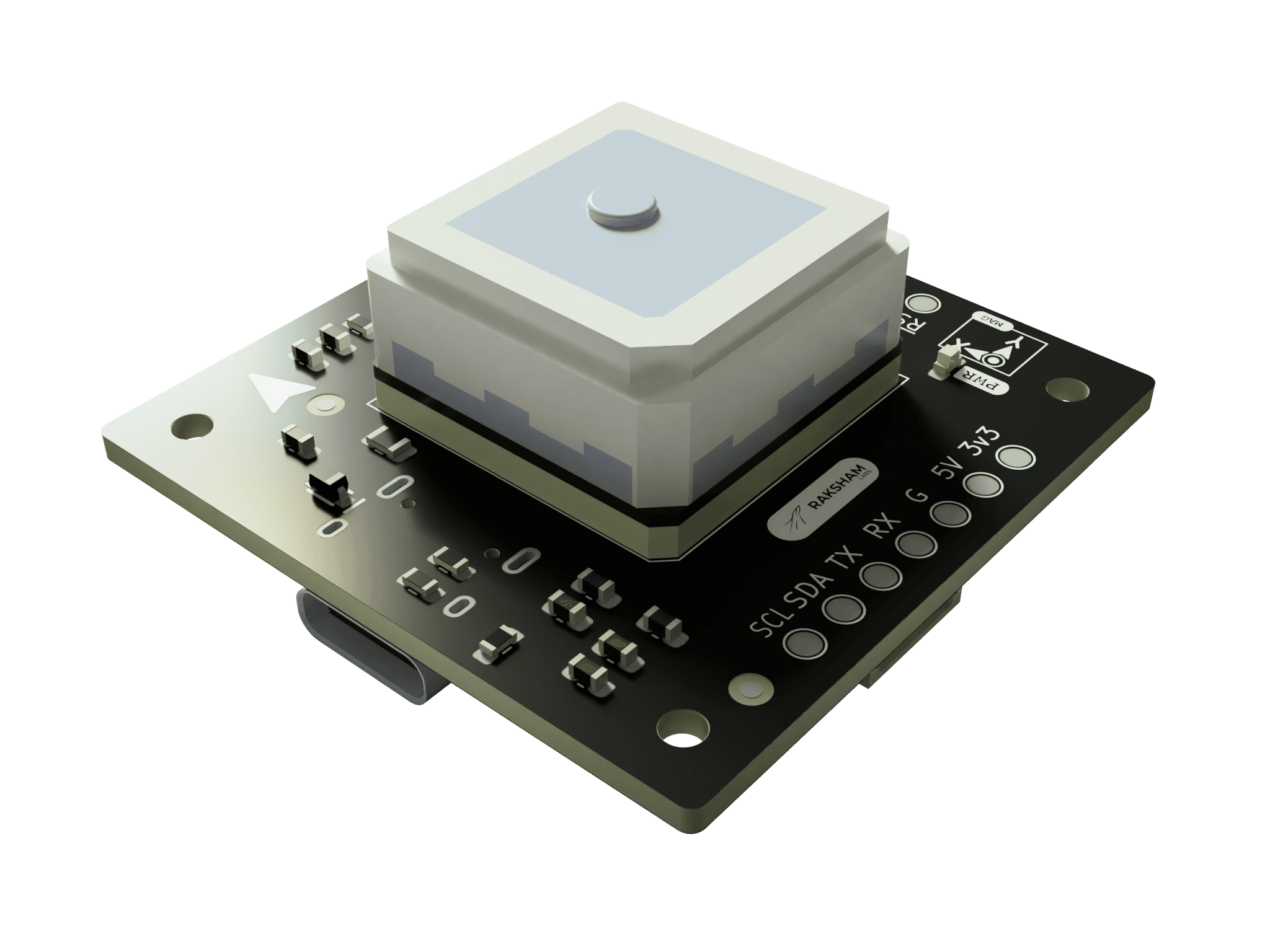
The KAMAL NAV GM1 is built around the u-blox DAN-F10N, an L1/L5 dual-band GNSS antenna module on the u-blox F10 platform. The dual-band front-end uses proprietary multipath mitigation to deliver 1 m CEP accuracy in urban and rotor-wash environments, where single-band receivers lose lock or drift. A SAW-LNA-SAW chain with an additional LTE B13 notch filter on the L1 path keeps out-of-band interference from onboard cellular modems and switching regulators from corrupting the fix.
An MEMSIC MMC5983MA 3-axis AMR magnetometer is integrated on the same 40 × 40 mm board. At 18-bit resolution with 0.4 mG RMS noise and built-in SET/RESET degaussing, it provides ±0.5° compass heading accuracy to the flight controller over I2C. The GNSS path hands off UART. Both share the same 6-pin JST SH 1.0 mm connector, so there is one cable between this module and the flight controller. A USB-C port exposes the full u-blox UBX interface for configuration and logging with u-center without rewiring.
A PPS LED blinks at 1 Hz on fix confirmation. A PWR LED confirms supply. ESD protection is fitted on all I/O lines. The board is RoHS compliant.
Use it for
- Primary navigation and compass heading in autonomous UAVs
- Dual-band GNSS validation in interference-heavy airframes
- Bench configuration and fix logging with u-center via USB-C
- Navigation redundancy and magnetometer cross-check in custom avionics stacks
- Clean GNSS and compass placement away from high-current wiring
At a glance.
All values are from the u-blox DAN-F10N datasheet (R04, 27-Jun-2025) and MEMSIC MMC5983MA datasheet (Rev A). Multi-GNSS figures use GPS + Galileo + BeiDou with SBAS enabled unless noted.
- GNSS chip
- u-blox DAN-F10N (F10 platform)
- Magnetometer
- MEMSIC MMC5983MA, 3-axis AMR
- Bands
- L1 (1575.42 MHz) + L5 (1176.45 MHz)
- Constellations
- GPS, GLONASS, Galileo, BeiDou, NavIC, QZSS
- Position accuracy
- 1 m CEP (multi-GNSS, SBAS enabled)
- Update rate
- 10 Hz (multi-GNSS) / 20 Hz (single GNSS)
- Cold start TTFF
- 28 s typical
- Hot start TTFF
- 2 s typical
- Tracking sensitivity
- -164 dBm
- Cold start sensitivity
- -145 dBm
- Velocity accuracy
- 0.05 m/s (50%, dynamic)
- Heading accuracy (GNSS)
- 0.3° (50%, dynamic)
- Magnetometer FSR
- ±8 Gauss
- Magnetometer resolution
- 18-bit, 0.4 mG RMS noise
- Compass heading accuracy
- ±0.5°
- Time pulse
- 1 PPS default (configurable 0.25 Hz to 10 MHz), ±30 ns RMS
- RF front-end
- SAW-LNA-SAW + LTE B13 notch (L1 path)
- Interface (flight controller)
- UART + I2C via 6-pin JST SH 1.0 mm
- Configuration interface
- USB-C (u-center compatible)
- Antenna
- Active on-board patch (RHCP), U.FL for external active antenna
- Protocols
- NMEA 4.11 (default), UBX binary
- SBAS
- EGNOS, GAGAN, MSAS, WAAS, BDSBAS, KASS, SouthPAN
- ESD protection
- Yes, on all I/O lines
- Operating temp
- -40°C to +85°C
- Supply voltage
- 5 V via JST SH connector
- Board dimensions
- 40 mm × 40 mm
- Compliance
- RoHS, HSN 85269190
- Country of origin
- India
How it works and how to wire it.
Interface wiring, antenna placement, NMEA and UBX parsing, magnetometer I2C address, and flight controller integration notes.
Wiring
Connect the 6-pin JST SH 1.0 mm cable between the module and your flight controller. Use the UART lines (TX/RX) for GNSS fix data and the I2C lines (SDA/SCL) for compass heading from the MMC5983MA. Default UART baud rate is 9600; ArduPilot and PX4 auto-detect or set this in the GNSS driver parameters.
Keep GNSS wiring away from ESC phase wires and switching regulators. The DAN-F10N's SAW-LNA-SAW front-end with the LTE B13 notch provides strong out-of-band rejection, but conducted noise on the supply or ground plane still degrades lock. A 10 µF + 100 nF decoupling pair close to the 5 V pin is recommended.
For external antenna use: connect a dual-band L1/L5 active antenna to the U.FL port. The module enables the antenna switch automatically; the integrated patch becomes inactive.
NMEA output
The default ASCII stream from the DAN-F10N uses GN talker IDs for multi-constellation output:
$GNRMC,123519,A,4807.038,N,01131.000,E,022.4,084.4,230394,003.1,W*6A
$GNGGA,123519,4807.038,N,01131.000,E,1,08,0.9,545.4,M,46.9,M,,*47
$GNGSA,A,3,04,05,09,12,24,,,,,,,1.2,0.9,0.8,1*27
Filter for $GNRMC and $GNGGA before parsing to skip GSV sentence floods. At 10 Hz with
GPS + Galileo + BeiDou enabled, GSV traffic is significant at 9600 baud; raise baud rate to 38400 or
115200 in u-center for high-rate operation.
Magnetometer
The MMC5983MA is accessible at I2C address 0x30 on the SDA/SCL pins of the JST SH connector. Use a SET/RESET command at startup and periodically thereafter to clear residual magnetization, especially after proximity to strong motor magnets. The built-in temperature sensor can compensate for thermal offset drift over flight.
u-center configuration
Connect the USB-C port to a PC. The module appears as a CDC virtual COM port. Open u-center, select the port, and set 9600 baud to start. All UBX-CFG messages are supported. Save configuration to flash with UBX-CFG-VALSET + layer = Flash, or via the u-center Configuration View save button.
Integration notes
Validate update rate, lock time, and antenna placement on the real airframe. Carbon structure, cameras, radios, and switching regulators change GNSS performance between a bench setup and a finished aircraft. The DAN-F10N is rated to ≤4 g dynamics and 500 m/s, covering all fixed-wing and multirotor platforms.
Pinout: 6-pin JST SH 1.0 mm
The UART lines connect to the DAN-F10N. The I2C lines connect to the MMC5983MA magnetometer. Both share the same 5 V supply pin. Wire only one GNSS interface mode at a time unless firmware explicitly supports both.
- 5V
- 5 V supply input. Powers both the DAN-F10N GNSS module and the MMC5983MA magnetometer via the on-board regulator.
- GND
- Ground reference. Keep the return path short and tied to flight controller ground.
- RX
- GNSS UART configuration input. Connect to the flight controller TX pin.
- TX
- GNSS UART data output (NMEA / UBX). Connect to the flight controller RX pin.
- SDA
- I2C data line for the MMC5983MA magnetometer. Default I2C address 0x30.
- SCL
- I2C clock line for the MMC5983MA magnetometer. Fast mode, up to 400 kHz.
Mechanical drawing
Board envelope, antenna ground-plane area, and side profile. All dimensions in millimetres.
NMEA sentence gate · C
Minimal filter that accepts common dual-band fix sentences before handing them to a parser. The GN prefix indicates multi-constellation output from the DAN-F10N.
bool raksham_is_fix_sentence(const char *line) {
  return strncmp(line, "$GNRMC", 6) == 0 ||
         strncmp(line, "$GNGGA", 6) == 0 ||
         strncmp(line, "$GNGSA", 6) == 0;
}
MMC5983MA single-shot read · C (I2C)
Trigger a measurement, wait for Data_Ready, then read 18-bit XYZ from registers 0x00-0x06. Assumes an I2C HAL with read/write byte functions.
#define MMC5983MA_ADDR  0x30
#define REG_XOUT_0      0x00
#define REG_STATUS      0x08
#define REG_CTRL0       0x09
#define BIT_TM_M        0x01
#define BIT_MEAS_DONE   0x01

void mmc5983ma_read_xyz(int16_t *x, int16_t *y, int16_t *z) {
  /* Trigger single measurement */
  i2c_write_byte(MMC5983MA_ADDR, REG_CTRL0, BIT_TM_M);
  /* Poll Data_Ready (typ < 8 ms at default BW) */
  uint8_t status = 0;
  while (!(status & BIT_MEAS_DONE))
    status = i2c_read_byte(MMC5983MA_ADDR, REG_STATUS);
  /* Read 7 output bytes: Xout[17:10], Xout[9:2], Yout[17:10],
     Yout[9:2], Zout[17:10], Zout[9:2], XYZout[1:0] */
  uint8_t buf[7];
  i2c_read_bytes(MMC5983MA_ADDR, REG_XOUT_0, buf, 7);
  uint32_t rx = ((uint32_t)buf[0] << 10) | ((uint32_t)buf[1] << 2) | ((buf[6] >> 6) & 0x03);
  uint32_t ry = ((uint32_t)buf[2] << 10) | ((uint32_t)buf[3] << 2) | ((buf[6] >> 4) & 0x03);
  uint32_t rz = ((uint32_t)buf[4] << 10) | ((uint32_t)buf[5] << 2) | ((buf[6] >> 2) & 0x03);
  /* Remove 18-bit offset (131072 = 2^17) to get signed counts */
  *x = (int32_t)rx - 131072;
  *y = (int32_t)ry - 131072;
  *z = (int32_t)rz - 131072;
}Questions, answered.
Navigation behaviour depends on antenna placement, airframe noise, and firmware configuration.